Pets, Plants, and Computer Vision
Header

Raspberry Pi Network Configuration

March 24th, 2014 | Posted by admin in code | computer vision | RaspberryPi | Uncategorized - (Comments Off on Raspberry Pi Network Configuration)

I’ve been playing with my Raspberry Pi a lot but getting the networking working on it is a pain. To me the /etc/networks/interface file is cryptic black magic. Here are a couple tools I am using to allow me to move between networks. Basically I have three networks setup: home, work, and mobile. The mobile connection is my phone’s tethering. The tethering allows me to setup the pi whereever I am and point the pi to the local network. To set up everything you need to edit /etc/network/interfaces and /etc/wpa_supplicant/wpa_supplicant.conf and make them look like the ones below. To test your changes on the pi while you are logged in you can use sudo ifdown wlan0 and sudo ifup wlan0. Basically you edit your wpa_supplicant.conf file on the pi and then use these commands to have the changes take effect.
My /etc/network/interfaces file:

My /etc/wpa_supplicant/wpa_supplicant.conf file. Make sure to add your own access points and passwords.

Another useful tool is fping. Fping can automatically ping every device on a network. So, for example, let’s say I go to a coffee shop and I want to use the pi. I turn on my cellphone tether, turn on the pi, and ssh in. I then edit the /etc/wpa_supplicant/wpa_supplicant.conf file, and either ifdown/ifup wlan0 or turn off the tether and reboot the pi. I then run ifconfig on my machine to get my laptop’s ip address on the coffee shop network. If my laptop’s IP is 192.168.42.3 I use fping to scan the entire subnet (e.g. 192.168.42.0 thru 192.168.42.255) . For example I can run:

sudo fping -s -g 192.168.42.1 192.168.42.255 -r 1

This will give me a list of IPs to ping. I can iterate through these IPs and find my pi.

This weekend I went to MicroCenter and picked up a couple of cool toys for the pi. The first thing I bought is a the Raspberry Pi IR camera. I didn’t have any IR LEDs to test with so in a pinch I used my TV remote control. TV remotes use IR light so it works as an IR flashlight. You can see the results of me taking a photo in a dark room.

Raspberry Pi IR Camera with TV Remote Flashlight.

Raspberry Pi IR Camera with TV Remote Flashlight.

I also picked up a 2600 mAH battery pack at Micro Center. I am really happy with its performance for $10. It has enough juice to run the pi remotely along with a bunch of peripherals like a small stepper motor.

ROS Industrial – Industrial Grade Awesome.

March 12th, 2014 | Posted by admin in automation | code | computer vision | demo | industrial computing | Industrial Internet | manufacturing | robots | Uncategorized - (Comments Off on ROS Industrial – Industrial Grade Awesome.)

)

Last week I had the pleasure of going to Southwest Research Institute (SwRI) to attend a ROS Industrial training session. I’ve been insanely busy for the past few months writing computer vision and other code for a fairly substantial Robot Operating System (ROS) project. I’ve been converted over to the dark side of ROS from OpenCV as ROS’s message bus, modular nature, and build tools are absolutely phenomenal. Hopefully a lot of that code will go back to the community once my employer signs the contributors agreement. I’ve gotten to know a lot about the sensor side of ROS but I wanted to round out my knowledge of the actuator side of things. This ROS-Industrial session seemed like a good place to do just this, and also get acquainted with more people working in manufacturing.

SwRI has always had a mythical place in my mind, mainly because all the cool kids got to go there when I got left behind at the lab. When I was in undergrad the RHex robot went there for testing, and while I was at Cybernet our DARPA Urban Challenge crew got to go there while I got to stay home and man the fort. A few months ago SwRI reached out to me and I asked if I could perhaps help with ROS Industrial. I’ve been trying to get some code and documentation done for them but I’ve been so busy I haven’t made as much progress as I would have liked. SwRI is currently the maintainer of ROS Industrial, and along with the OSRF they are making great strides to improving the usability of ROS in industrial settings.


The tutorials published and presented by SWRI were excellent and very well polished. They made a conscience effort to have the tutorials go from high level tutorials for decision makers all the way to nuts and bolts code introductions for programmers and integrators. I really hope the publish more of the tutorials as they were exceptionally well put together, relevant, and well thought out. To be certain what SwRI is trying to accomplish with ROS industrial is no small feat, as you can see from the video of of their 2013 Automate Demo video at the top of the page. At the the ROS Industrial training session SwRI walked us through the high level architecture of this system (all of the components are FOSS software!) at a level where I think I could probably recreate it given a few weeks of coding. For a single day session I thought they covered a lot of ground and the demos they had of ROS industrial were incredible. In addition to the 2013 Automate demo they had a another robot doing arm doing an exceptionally complex deburring maneuver around an complex bent puzzle piece. Another demo showed an on-line object tracking and path planning demo for robot finishing of automotive parts. I capture a few of the demos in a short video.

In addition to the tutorials I picked up a few new and interesting libraries from the other attendees. One that stood out was MTConnect which is a free and open XML/HTML standard for robots and CNC software to communicate their state and status. It looks pretty cool and there are already some open libraries out on github. Another cool suite of tools is this EPICS PLC communication package put out by Paul Scherrer Institute in Switzerland. There also seems to be a mirror of it by Argonne National labs. Apparently CERN uses a lot of PLCs and they were insistent that all PLCs used at CERN had open Linux drivers. EPICS stands for Experimental Physics and Industrial Control System. I haven’t looked too deeply into the package but it seems like it could be handy.

I’ve caught my breath. Time to start another company.

March 10th, 2014 | Posted by admin in automation | computer vision | Electronics | entrepreneurship | Internet of Things | TempoAutomation - (Comments Off on I’ve caught my breath. Time to start another company.)

I quit my well paying job as a hired gun for post-funding start-up in a Boston to return to the world of eating boiled news papers and sleeping on the floor of a hacker squat. I feel like I have caught my breath and I am ready to try again. After a drawn out courtship I have decided to come on as the software lead and co-founder of Tempo Automation. We’re after the very seductive idea of building robots and helping individuals and other engineers build, design, and test their own printed circuit boards (PCBs). The immediate goal is to put a pick and place robot that can go in every hacker space and engineering office around the world. Every shop with a 3D printer and a laser cutter should have one of our machines. The end-game is to convert these simple robots from merely a pick-and-place to a one stop PCB factory that does milling, solder deposition, pick and place, reflow, and ultimately AOI, programing, and testing. Raw materials go in one side, PCBs come out the other side. Idea bits get converted into atoms. We want to do for electrical engineering what the Rep-Rap and Makerbot did for mechanical engineering.

Tempo -- Maker Faire NYC 2013

Tempo — Maker Faire NYC 2013

I am really, truly, excited to be working on an interdisciplinary team once again. Robotics is a field where people still take pride in using the word “engineer” in their title. When I say engineer I mean people who want to fix problems; not just wax brass on the Titanic by writing bank software or slick advertising webpages. Being a big “E” engineer means you get to put down the mouse, pick up a multimeter and some hex keys, and build some awesome. I feel like I couldn’t have found a better set of co-founders. Jeff McAlvay embodies everything I want in a non-technical founder: he knows how to run a business but he doesn’t want to be an executive. Jeff is sincere about the things that are important: solving the problem, learning the technology, and helping the customers. I am also in awe of Jeff’s time at McMaster-Carr; McMaster is such a great organization and I want to learn more about how people like Jeff made it run so perfectly. I am also excited to be working with Tempo’s other co-founder and mechanical lead, Jesse Koenig. Jesse serves as a great counter balance to my personality. He is detail orientated where I would be hand wavy, he likes to work on the books while I do community stuff, and he seems to know just when to force me to listen and when to leave me alone and code. If this were a guy-cop-buddy movie Jesse would be the good cop to my bad cop, and Jeff would be the affable but stern police commisioner providing us with the resources to clean up the mean streets of PCB City. Rounding out our team are Prof. Peter Vajda a visiting Computer Vision professor at Stanford and Jon Thorne, one of the best all around mechanical engineers I’ve met. Ted Blackman and Cody Daniels, from the 3Scan crew are also lending us their software and hardware expertise.

I am also amazed by the community that Jeff and Jesse have chosen to surround themselves with. The people at MI7 and Langton Labs are fantastic and it reminds me so much of home at Arbor Vitae. The first thing I said when I walked into the office is that it felt like home. Jeff has also done a fantastic job of organizing and growing a hardware community in San Francisco and I am really excited to not just work on this project but get the privilege to share it with others.


Finally, I am really excited about our technology stack as it lets me use my knowledge of computer vision within a suite of new software. Things are still solidifying but it looks like I will be working not just with a lot of open software but also a lot of open hardware (and hopefully building a lot of it too). I am looking forwarded to learning a lot about Meteor, javascript, bottle/flask, and potentially ROS in the coming weeks. There is still a lot of code to write but I can already see the parts coming together.

Will this venture make us so insanely rich that we can jump Tesla’s off our yachts? Probably not, but it is an idea with a market need where we can grow a reasonable business. We also won’t ever have to talk about our “product” as being the end-all and be-all social/mobile/local/viral cloud analytics marketplace as a service. We’re doing something that matters. Something that helps make the world a better place by enabling people to build their dreams and needs. To be sure we can’t make a business if we don’t make money, and I am sure we can, but what is more important is that we’re spending every waking moment doing something we love and that we feel really matters. Most important of all I get to spend the next few years teaching people how to build electronics and use robots to make their ideas a reality. I haven’t been this happy in a long time.

Fish Eye Lens Dewarping and Panorama Stiching

August 15th, 2013 | Posted by admin in code | computer vision | OpenCV | python | SimpleCV | Uncategorized - (Comments Off on Fish Eye Lens Dewarping and Panorama Stiching)
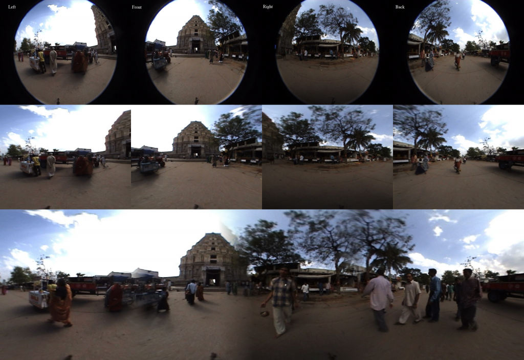
The entire panorama stitching process as one big image.

The entire process as one big image.

I was challenged to see if I could create 360 degree view panoramas from a series of fish eye images taken at right angles to one another working from this tutorial. I modified the code from my 360 lens dewarping project to create the code for this project which you can check out here. There are roughly two types of fisheye images, circular fisheye lens that map a sphere onto the image plane, and full frame fisheye lens that map the input image to the entire rectangular image plane. The data I was working with was from a circular fisheye, which is significantly easier to reason about.

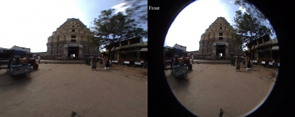
There are a couple of different ways you can approach the problem of fisheye lens dewarping. The first, and probably more robust approach is to develop a camera lens model that accurately represents the fish eye lens distortion, and apply that lens dewarping to the image. In the absence of a calibration data, particularly for full frame fisheye’s, you would then need to manually tune the camera model parameters to dewarp the image, or use some of the image data to get a back of the envelope approximation of the camera parameters. The second, and in my opinion the easier, albeit slightly less robust approach, is to create a mapping from the output image pixels in terms of phi and theta in a circular coordinate system, and map that to pixels in the input image. The basic idea is that in the output image each pixel represents some steradian on the input image. The best way to think about a steradian is as a “pixel” on the sphere, or the square mapped out by latitude and longitude lines. Each steradian then maps to a point on the image plane, which you can calculate by doing a spherical to Cartesian conversion and dropping the value that is in the normal to the image plane.

Dewarped image on the left and input circular fisheye image on the right.

Dewarped image on the left and input circular fisheye image on the right.

For example, in my code, I first create an output image and assume each x and y position on the image maps to somewhere roughly between 0 and 180 degrees (0,pi) for both phi and theta. In my model the direction pointing straight out of the camera is called y, so I then do a spherical to Cartesian conversion assuming a unit sphere. Since the unit sphere is at the origin, I shift the sphere and rescale it to be of unit length, and then multiply the result by the input image dimensions. An easier way to think of it is this:

Destination image pixel (X,Y) –> scale to unit length –> convert to between zero and pi –> do spherical to Cartesian conversion –> rescale to get values between 0 and 1 –> multiply by the input image dimensions to get input pixel (X,Y).

The map is a bit tedious to create, but once you have it, OpenCV can really quickly push pixels around and give you a result.

Panorama dewarped from four fish eye images.

Panorama dewarped from four fish eye images.

The next step was to do the panorama stitching. To do this I first matched ORB keypoint between two successive pairs of images. Since I knew the images were vertically aligned, all I needed to calculate was the x value that is the horizontal offset. To do this I used the median x difference between the two sets of points (the median in this case acts as a poor man’s RANSAC to remove outlier matches). I then used this x offset to construct an alpha mask that I could use to smoothly blur the two images together. I played with this for a little while and I found a nonlinear mapping seemed to work a lot better. There are some problems with the images as they don’t seem to be taken at the exact same time, but for a half a day’s worth of work I am very pleased with the results.